Once in awhile, I like to return to my "roots" and do a bit of old-fashioned hardware hacking. Digging through an old parts box, I noticed a couple of solar panels still in the packaging I hadn’t gotten around to doing anything with. So I decided to have some fun and try to build a solar-powered battery charger, and also do it in the most inexpensive way possible.
The following images show each step in the process required to build a fully functional solar battery charger. If you are uncomfortable with a soldering iron, power tools, or taking apart electronic devices then it is advisable to skip this "how-to" until you are ready. Please also remember to be safe when disassembling electronic devices. I am not responsible for any injuries you could potentially receive following these instructions!
First, I removed one of the panels from the packaging and measured the output voltage; it was slightly over 5 volts.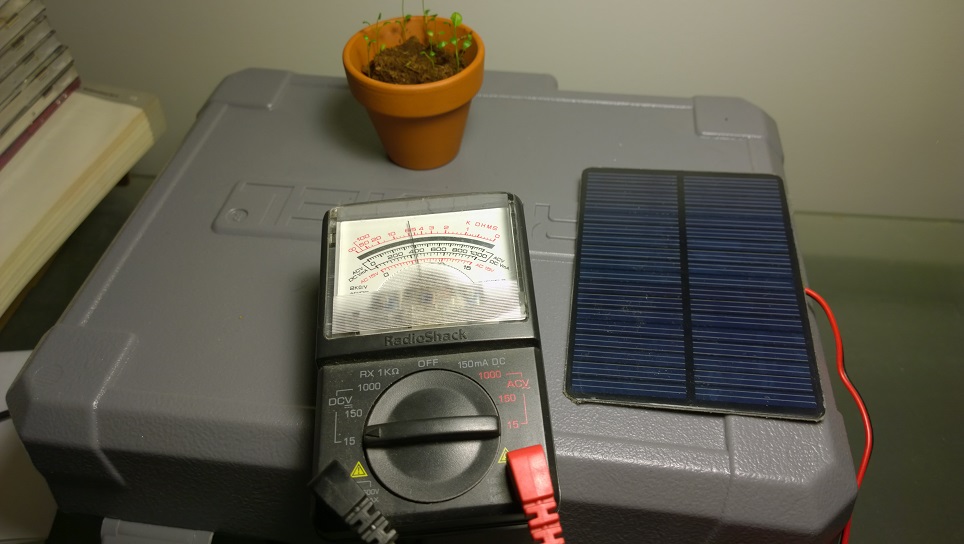
This was an older generation of an Energizer brand battery charger I procured for around $3 on discount.
I then unplugged the charger and removed the front of the case.
This is a shot of me measuring rectified DC voltage with the charger plugged in. My voltmeter measured around 4.8 volts DC.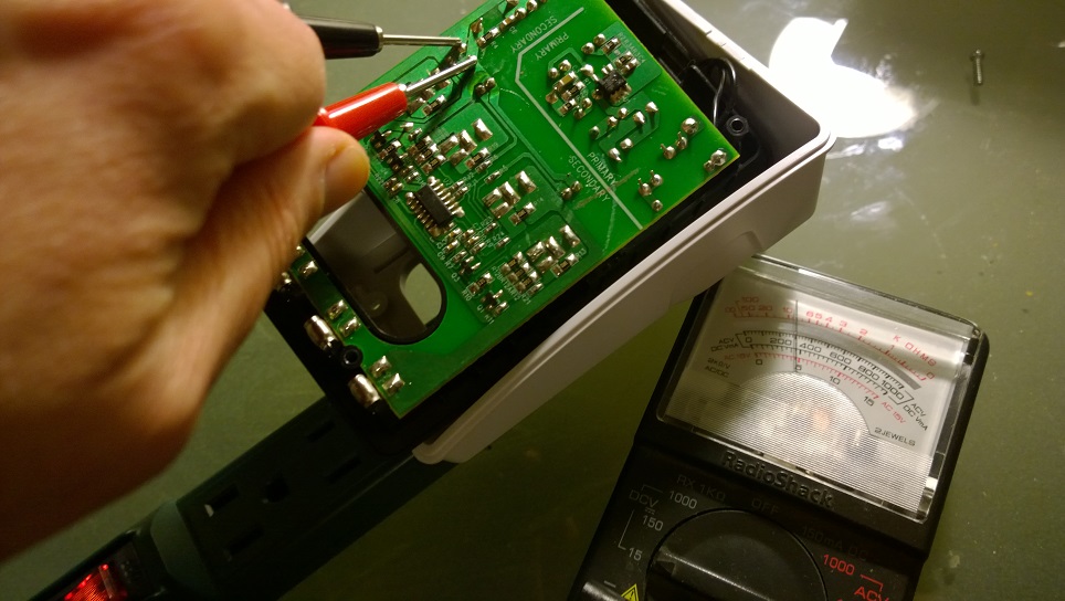
A view showing the two black wires leading from the plug to the circuit board. 
After once again unplugging the charger, I snipped the two black wires, removing the board from the case.
It was almost as if this board was designed to be hardware hacker friendly. The power supply is situated at the top section of the circuit board, helpfully labelled underneath. I used a dremel tool to cut a straight line across the entire width of the board, removing the power supply.
The power supply portion of the board completely removed. I kept it though, because with a couple of tweaks it will be perfect to use for powering a prototype board.
Top view of the board that I used for this project.
Bottom view, I needed to remove the battery contacts from the board. This required desoldering, so I plugged-in my soldering iron.
The case made a great "holder" to keep the board in one place while I used an iron and desoldering bulb to remove solder from the battery contacts.
A view of the circuit board after the contacts had been removed.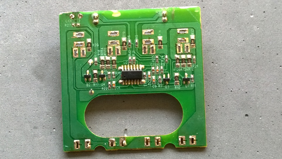
Top view of the board with the contacts removed. The board has a much thinner profile now.
This is a tablet case I purchased for $1 at a discount shop.
I separated the top and bottom portions of the case, using a sharp knife to cut the stitching.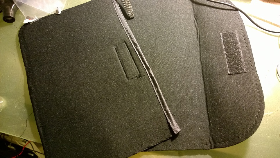
A pack of sticky mounting tabs, purchased for a buck at the same store I bought the tablet case. I use these to mount the solar panels to the bottom of an old iPad case I had lying around.
I wired the solar panels in parallel, and soldered the wires at the same location on the board where I measured the secondary voltage with my voltmeter. Because I am only charging two batteries, I removed the second LED, and soldered leads from two AA battery holders to the same places on the circuit board the first set of battery terminals were originally.
Before I secured any of the parts, I took the apparatus outside to test the charger in full sunlight, testing its ability in the "real world" to recharge dead batteries. 
It worked! So I continued — velcro from the cheap tablet case was glued on the edge of the case near the circuit board. I sliced and glued pieces of the $1 tablet case on the other side to provide padding for the panels and board when "shut."
Case closed!
Disclaimer: I am not associated or employed by any company producing hardware reviewed on this site.


Leave a comment